


Manufacturer's Specifications:
-
Power Output: Stereo, 600 watts minimum continuous power per channel, both channels operating into 8-, 4-, or 2-ohm loads; mono, 1,200 watts minimum continuous power into 16-, 8-, 4-, 2-, or 1-ohm loads.
IHF Dynamic Headroom: 1.7 dB.
Power Bandwidth: 20 Hz to 20 kHz.
THD: 0.005% maximum, both channels operating at any frequency from 20 Hz to 20 kHz and at any power level from 250 mW to 600 watts per channel in stereo or from 250 mW to 1,200 watts in mono.
IM: 0.005%, both channels operating for any combination of frequencies from 20 Hz to 20 kHz if instantaneous peak power is 1,200 watts per channel or less in stereo or 2,400 watts or less in mono.
Frequency Response: 20 Hz to 20 kHz, +0,-0.25 dB; 10 Hz to 100 kHz, +0,-3 dB.
Hum and Noise: 105 dBA below rated output.
Damping Factor: Greater than 40.
Input Impedance: Unbalanced, 20 kilohms; balanced, 40 kilohms.
Input Sensitivity: 1.4 or 2.5 V, selectable.
Power Guard: THD kept below 2% and clipping prevented with up to 14 dB of overdrive at 1 kHz.
Power Requirements: 120 V, 50/ 60 Hz, 2 to 24.5 amperes (12 amperes, UUCSA).
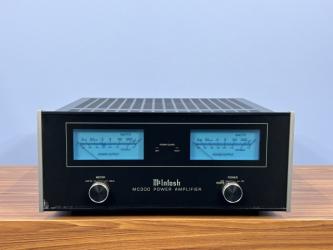
The MC2600 is the first piece of McIntosh equipment that I have ever formally reviewed, and what a piece it is! All 130 pounds of it! I have listened to arid tested various McIntosh amplifiers over the years, and I have been generally impressed with the build quality and the measurements of most of the gear that I have tried out.
The amplifier under review, McIntosh's current best effort, is rated at 600 watts per channel into 2-, 4-, or 8-ohm loads in stereo or 1,200 watts mono into 1-, 2-, 4-, 8-, or 16-ohm loads. The MC2600 replaces the MC2500, which was a similar-sized, top-of-the-line unit rated at 500 watts per channel. The MC2600 has 50% more output transistors than the MC2500, more than twice as much energy storage in its filter capacitors, somewhat higher overall efficiency, both unbalanced and balanced inputs, much lower measured distortion, and more than twice the peak current into mis matched loads (i.e., loads that drop to values much lower than the matching impedance of the output autoformer tap used). The MC2600 is said to drive loads down to 20% of the rated tap impedance before current limiting sets in. Most impressive! This amp should drive the most difficult and demanding load with ease.
-
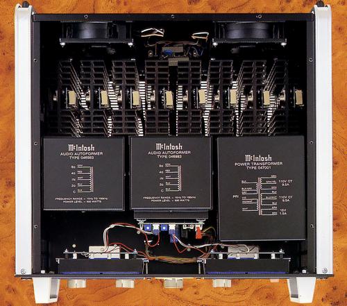
A good part of the MC2600's weight is in the output autoformers that allow matching to the various loads. An autoformer is a special transformer that uses a single tapped winding, instead of separate primary and secondary windings, to get the various impedance ratios desired. It is easier to make a good autoformer than a normal transformer, especially at the impedance levels used here.
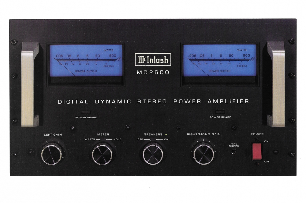
Peak output currents of some 100 amperes per channel are mentioned in the McIntosh technical description but are not listed in the formal specifications. Very low distortion, less than 0.005%, is claimed over a frequency band of 20 Hz to 20 kHz at rated power or below. Interesting features include front-panel level meters with continuous or peak-hold reading modes and McIntosh's Power Guard circuitry that prevents the amplifier from being overdriven beyond about 1% clipping distortion.
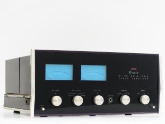
Below the output level meters are a number of rotary controls: "Left Gain," a two-position "Meter" function switch, a two-position speaker on/off switch with LED indicators, and the right gain control (which also functions as the mono gain control when the amp is in mono mode). To the right of the controls are a headphone jack and a rocker-type "Power" switch, which is also the line circuit breaker. A pair of beefy rack handles completes the front panel.
-
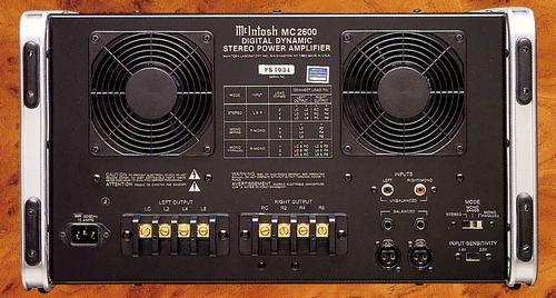
On the rear panel, near the top, are two variable-speed exhaust fans. Between them is a chart detailing the proper input and output connections and the loadings to use for the amplifier's stereo, bridged mono, and parallel mono modes.
In a row below the fans are the power-cord connector, four-terminal barrier strips for each channel's load connection, three pairs of input connectors (phono for unbalanced in puts, 1/4-inch phone jacks and XLR for balanced inputs) and two slide switches for "Input Sensitivity" and operation al "Mode." Both sliders have recessed toggles that are switched with a small screwdriver blade. The sensitivity switch has two positions, 1.4 and 2.5 V for full output, while the "Mode" switch has three positions: "Stereo," "Mono (Bridge)," and "Mono (Parallel)." The gold-plated output terminals are very unusual and appropriate to this amplifier's high current-output capability.
The normal connecting screws, used with small-gauge wires or spade lugs, terminate in cylinders 1/4 inch in diameter. Removing these screws allows the removal of the cylinders, leaving holes that can accommodate up to 1/4-inch wires. These wires can then be clamped securely with the very large set screws provided as replacements for the normal screws. My only complaint with this otherwise out standing output connection scheme is that the barriers between the screw terminals aren't spaced widely enough to accept large connecting spades like the ones on the Cardas Hexlink speaker cables I use.
-
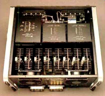
Inside the amplifier, the power transformer and both out put autoformers are lined up across the amp, toward the front. Occupying most of the internal area toward the rear is a line of eight heat-sinks, each with five TO-3 metal-can power transistors along with associated interconnecting p.c. boards.
An internal dividing piece of metal, about a third of the way up from the bottom, serves to mount the transformers.
This plate is strengthened and supported by a perpendicular plate below it, attached to the amplifier's bottom plate, which also holds the four main power-supply filter capacitors (two per channel). Mounted to the terminals of the main filter capacitors are two p.c. boards that interconnect the filter capacitors and distribute power-supply voltages and audio output current from the heat-sink assemblies. Each heat-sink attaches to the appropriate board via a connector.
This makes for easy servicing of the output stage, as you can remove the whole heat-sink without soldering. Support for the heat-sinks is supplied by the transformer mounting plates at the front of the amp and by another horizontal plate, the same height as the transformer mounting plate, at the rear of the unit.
-
Mounted in front of the filter capacitors are two p.c. boards that contain the front-end circuitry for each amplifier channel. The main power-supply rectifier bridges are mounted to the right side panel, near the bottom front.
At the top of the amp, toward the front, a p.c. board mounted to the middle autoformer carries the circuitry for the front-panel meters. At the bottom left rear, two more p.c. boards are mounted behind the input connectors and sensitivity and "Mode" switches. The input circuitry is contained on the board behind the switches; the board behind the phone and XLR jacks serves mainly to connect these two balanced inputs in parallel.
The overall chassis enclosure is made up of separate pieces forming the sides, rear and front, and top and bottom. Overall, it is built like a tank and certainly can stand up to the rigors of professional use. One touch that I like is the presence of feet on the rear as well as the bottom, so the amp can be put on its back without having the rear panel's protrusions touch the floor. These feet are mounted on inch-wide aluminum bands that attach to the front panel and side plates and are removed if the amplifier is rack-mounted. For rack mounting, threaded holes in the sides of the amp can be used to attach it to slides. This will allow the MC2600 to be pulled out like a drawer while remaining supported.
-
Circuit Description
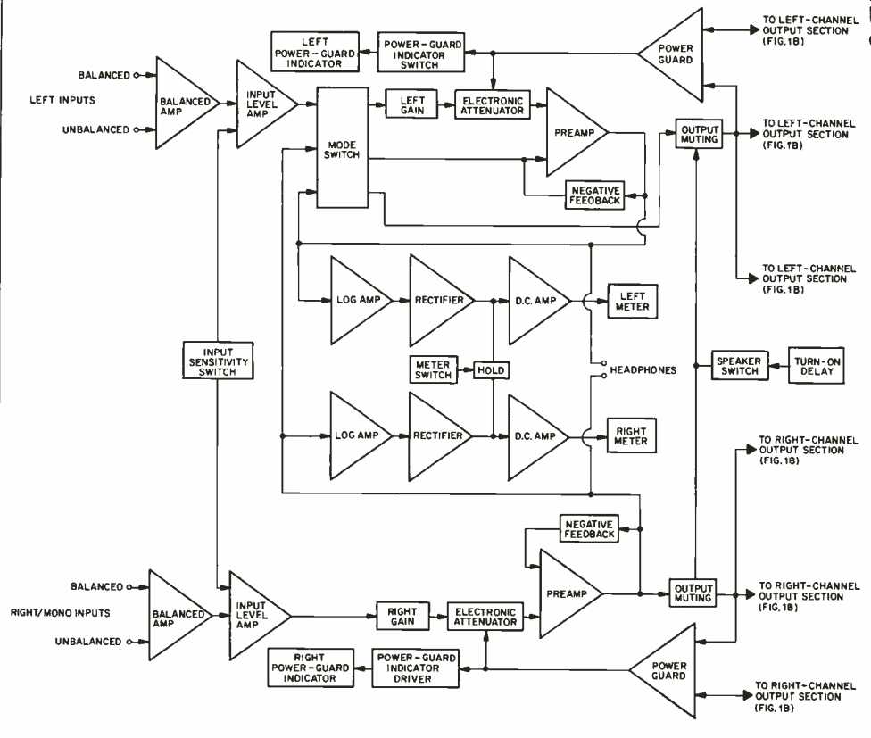
Fig. 1A--Block diagram of input stages.
-
Block diagrams of the MC2600 are shown in Figs. 1A and 1B. As can be seen, this is a sophisticated and rather complicated system. The actual signal circuitry starts with an input differential amplifier (which accommodates balanced or unbalanced inputs) feeding an adjustable-gain level amplifier. This two-stage circuit uses a dual NE5532 type op-amp IC. The gain of the second stage can be selected by switching the feedback resistor to set the MC2600's input sensitivity at 1.4 or 2.5 V for full output.
Following the input level amplifier is the "Mode" switch. As noted, this switch selects stereo, bridged mono, or parallel mono operation.In bridged mono mode, the "Mode" switch's input comes only from the right-channel preamp output; the left input level amp's output is not used. This right-channel signal then passes into the inverting input of the left channel's preamp input, with the net result that the channels' outputs are of opposite polarity. This is, of course, what is required for normal bridged operation, and the load is connected between the hot terminals of the two channels' outputs.In the parallel mono mode, the left channel's preamp is bypassed; the right channel's preamp output goes, via the output muting relay, directly into the left channel's power amplifier input. The result is that the two channels' outputs are identical, in-phase signals.
Note that, in both mono modes, the Power Guard function is controlled from the right channel's signal path. In parallel mono operation, the user must tie the two channel outputs together, hot to hot and ground to ground, at the output terminals. Load matching occurs when the load is half the nominal value of the output hot taps that are tied together.
For instance, a 1-ohm load is driven to 1,200 watts by tying the 2-ohm taps together. As another way of looking at this, imagine not tying the outputs together and driving two separate 2-ohm loads. Here, 600 watts would be delivered to each load for a total of 1,200 watts. A basic network theorem states that if there is no potential difference between two points in a network, they can be tied together with no effect. The two channels' outputs are moving together in phase and presumably are at the same amplitude, so we can short them together. When this is done, we have a composite 1-ohm load being fed 1,200 watts. With solid state amplifiers in general, paralleling channel outputs is decidedly not a good idea, as any difference between channel outputs, especially d.c., makes a large common mode current to flow between the channels, usually causing destruction of the output stage. In the case of the MC2600, the d.c. resistance of the autoformer windings and careful matching of levels make the scheme workable.
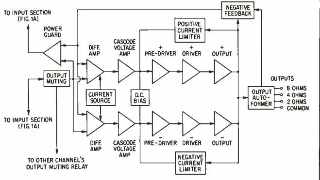
Fig. 1B--Block diagram of output stages.
Referring to Fig. 1A, it can be seen that, following the mode switch in the left channel and the input level amplifier in the right channel, are the gain controls, the Power Guard circuit's electronic attenuators, the preamp blocks, and the output muting relays that precede the actual (finally!) power amplifier circuitry.
In stereo operation, the "Mode" switch passes each channel's signal straight into the gain control and other following circuitry, and the amplifier functions as two independent channels.
Fig. 3-Square-wave response, measured at 8-ohm tap, for 10 kHz with 8-ohm load (top), 10 kHz with 2-µF capacitance across 8 ohms (middle), and 40 Hz with 8-ohm load (bottom). Scales: Vertical, 5 V/div.; horizontal, 20 µS/div. for 10-kHz traces, 5 mS/div. for 40 Hz.
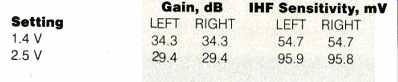
Gain and sensitivity were measured first, for both positions of the rear-panel sensitivity switch and with 8-ohm loads on the 8-ohm output taps (Table I). Voltage gain is on the high side, compared to the usual 26 dB or so, especially with the 1.4-V sensitivity setting.
Frequency response on the 4-ohm taps is shown in Fig. 2.
The three curves show the effect of loading. Output impedance is fairly low, as evidenced by the close similarity of the curves, and the high-frequency response, at least up to 200 kHz, is nicely behaved. Related to frequency response is rise- and fall-time for step functions or edge transitions in square waves. For the MC2600 at an output level of 10 V peak to peak, rise- and fall-times were, respectively, about 2.0, 2.1, and 2.5 uS for 8 ohms on the 8-ohm tap, 4 ohms on the 4-ohm tap, and 2 ohms on the 2-ohm tap.
The top trace of Fig. 3 shows the amp's response to a 10-kHz square wave with 8 ohms on the 8-ohm tap. This is the fastest of the three conditions previously described; the corner shape gets progressively more rounded as you go down the output taps. The middle trace of Fig. 3 shows the effect of a 2-uF capacitive load paralleled across the 8-ohm resistance. The ringing seen here is fairly typical of solid state amplifiers. In the 40-Hz square wave in the bottom trace, there is somewhat more tilt than I like to see. This relates to the fact that response is nearly 1 dB down at 10 Hz, as was seen in Fig. 2.
Distortion properties were looked at next. Figure 4 is a plot of SMPTE-IM distortion and 1-kHz .THD + N as functions of output power. Loading was 4 ohms on the 4-ohm tap. Results are shown for the left channel, which read slightly higher than the right. The THD + N curve is dominated by circuit noise below about 80 watts, as shown by the curve's rise of 20 dB per two decades of decreasing power. The IM emerges out of the noise at about 30 watts.
Figure 5 shows THD + N versus frequency at a number of power levels. Notable here is the relatively small rise in high-frequency distortion at any given power. The curves for 10- and 1-watt levels essentially show circuit noise again, but it is of interest that distortion at low levels doesn't poke up above the noise level at higher frequencies. McIntosh sure has got it down with regard to low distortion at high power! Thirty to 40 parts per million (0.003% to 0.004%) is very good measured performance.
Figure 6 is a spectrum analysis of the distortion products at the 10-watt level, again for the left channel. A time waveform of this signal, as I usually show, would just look like random noise. In the figure, a second-harmonic component of about 0.00018% is visible along with a third harmonic of about 0.0017%. In the right channel, both the second and third harmonics measured about 0.0003%.
Output noise as a function of the sensitivity setting at various bandwidths is covered in Table II. The measurements made wideband and from 22 Hz to 22 kHz are higher in the right channel due to the presence of a 60-Hz hum, probably induced from the power transformer. The hum appears in the form of a low-order square wave (that is, one with little upper harmonic content).
Use and Listening Tests
During the early part of the MC2600's stay, I used it as the bass amplifier in biamping Martin-Logan Monolith III speakers. In this service, bass was well damped and extended with, of course, enormous and effortless power delivery.
When I started to listen to the amplifier wide-range, driving the Martin-Logans (with their own passive high-level cross over) and several other speaker systems, I got a pleasant surprise. I had subconsciously expected the MC2600 to sound powerful but perhaps somewhat irritating and undistinguished. Surprise! It sounded very good. Frequency balance was very good, space and resolution were good, and-a high listening priority for me-it was not edgy or irritating. I found myself using the amp quite a bit in listening to a lot of music, and it was quite musically satisfying. In use, there were no unwanted noises like turn-on or turn-off thumps, just perfect operation. This is a very competent amplifier whose performance is appropriate for its position as McIntosh's flagship.
| Type | Stereo power amplifier |
| Output (sine wave continuous output) | Stereo : 600W + 600W (2 Ω, 4 Ω, 8 Ω) Mono : 1,200W (1 ohm, 2 ohm, 4 ohm, 8 ohm, 16 ohm) |
| Output impedance | Stereo : 2 Ω, 4 Ω, 8 Ω Mono Parallel : 1 Ω, 2 Ω, 4 Ω Mono bridge : 4 Ω, 8 Ω, 16 Ω |
| Output frequency band | 20 Hz to 20 kHz |
| Total harmonic distortion factor (20 Hz to 20 kHz) |
Stereo : 0.005% or less (250 mW ~ 600W, both channel operation) Mono : 0.005% or less (250 mW to 1200W) |
| Intermodulation distortion factor (20 Hz to 20 kHz) | Stereo : 0.005% or less (peak 1,200W or less per one channel, both channels operating) Mono : 0.005% or less (peak, 2,400W or less) |
| Frequency Band (at 1W output) | 20 Hz ~ 20 kHz + 0 -0.26 dB 10 Hz ~ 100 kHz + 0 -3dB |
| Signal-to-noise ratio | 105 dB or less (at rated output, A-weighted) |
| IHF Dynamic Headroom | 1.7dB |
| Damping factor | 40 or more |
| Input impedance | 20k Ω (unbalanced) 40k Ω (balanced) |
| Input sensitivity | Switching to 1.4 v, 2.5 v |
| Power Guard | Overdrive at 1 kHz up to 14 dB THD within 2% |
| Accessory function | Power meter for lighting with voltage regulator WATTS/HOLD meter display changeover switch Left and right independent gain volume Headphone monitor terminal Speaker on/off switch |
| Pwer | 100 VAC, 50Hz/60Hz, 2A ~ 24.5A, 15A, UL/CSA |
| External dimensions | Width 483x Height 267x Depth 457 mm (including terminal) Handle Clearance 44 mm |
| Weight | 59kg |
DocumentMaster/us/Legacy/MC2600-FS-OWNERS.pdf?rev=34f3b1f41fa1433fb68a849fbca4e854&revision=34f3b1f4-1fa1-433f-b68a-849fbca4e854
chrome-extension://efaidnbmnnnibpcajpcglclefindmkaj/https://www.mcintoshlabs.com/-/media/Files/mcintoshlabs/DocumentMaster/us/Legacy/MC2600-FS-OWNERS.pdf?rev=34f3b1f41fa1433fb68a849fbca4e854&revision=34f3b1f4-1fa1-433f-b68a-849fbca4e854